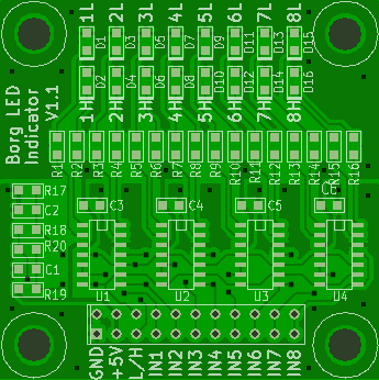
This PCB has 8 inputs connected to 2 comparators each which drive a LED. One LED is for low level and one LED for high level. If both LEDs are dark the voltage is somewhere between the two thersholds.
Schema, production files in the format needed for Seeed Studio.
Connect a power supply voltage between 5.5V to VCC and GND. Connect the signals to be watched to the inputs IN1 to IN8. When an input is low the LED nL lights, when an input is high the LED nH lights. When the input voltage is between the two thresholds both LEDs are dark.
| 1,2 | GND | Power ground. |
| 3,4 | VCC | Power supply, 5V. |
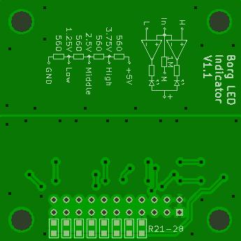
| 5 | L | Low threshold voltage. |
| 6 | H | High threshold voltage. |
| 7,8 | IN1 | Input 1. |
| 9,10 | IN2 | Input 2. |
| 11,12 | IN3 | Input 3. |
| 13,14 | IN4 | Input 4. |
| 15,16 | IN5 | Input 5. |
| 17,18 | IN6 | Input 6. |
| 19,20 | IN7 | Input 7. |
| 21,22 | IN8 | Input 8. |
| Ref. | Count | Description |
|---|---|---|
| - | 1 | Borg Level Translator PCB |